Author: Dennis J LeGear, Capt. Ret. Oakland Fire, CA
Uncommon thoughts about commonly used suppression equipment: information to aid in the selection of proper handline hose diameter (fire hose's dirty little secret).
Introduction: History Repeating
The fire service is once again focusing on a topic that garnered a lot of attention in the 80’s and 90’s. Many are now revisiting the concept of attaining higher than standard flows through 1.75-inch hand-lines. 1.75-inch hand-line flows of 250gpm are being considered. This flow in small diameter hand-line is, in many ways, damaging to all fire ground operations because it limits the functional envelope of the stretch to around 200 feet due to high friction loss. Creating two distinctly different flows from one size hose-line also adds to fire ground confusion by complicating pump operations and line selection.
Company level issues begin with a tunnel vision that sees a hose stretch of 200 feet as sufficient for the commercial fire ground. A limited stretch length capacity will cause the Officer and the Engineer to consider poor engine placement, blocking critical truck placement real estate in front of and at the corners of buildings. There is great potential for time intensive and dangerous hose pack deployment if the stretch should fall short. It complicates pumping operations by producing two friction loss numbers in one size line. Other complications likely to arise are: two nozzle pressures (NP) in a single fixed orifice nozzle system, a set of stacked tips, or the complicated automatic hand-line nozzle. It increases likelihood of line failure do to greater internal forces created by high pump discharge pressure. It complicates multiple hand-line operations off one pump due to high pump pressure differences between large and small hand-line sizes attaining large flows.
Command and Chief level issues will include the following negative impacts on the fire ground. There will be an inability to determine flow by simply looking at the deployed hand-lines. Large hand-lines and small hand-lines should always be spec’d in contrasting jacket colors, thus aiding command in determining fire flows. There will be a reduction in total flow capacities on the fire ground because, as pump pressure increases pump capacity decreases. There will be difficulty in placing second alarm companies, especially trucks, due to initial alarm engine companies striving to get within their 200 foot envelopes of function. The increased complexity of operations, training, and equipment purchasing will have been submitted to for a slightest possible benefit.
The author has spent over a decade studying this, and the true necessity of keeping it simple cannot be overstated. The goal of most fire departments should be a single small attack line flow of 160-185gpm (staffing of 2-3 firefighters) and a single large attack line flow of 250-300gpm (staffing of 3 plus firefighters). This should be generated in two distinctly different hose sizes while maintaining a reaction force and charged hose-line weight that produces a mobile attack hand-line capable of aggressive interior operations. If you have not yet read Nozzle Dreams, the author urges you to do so before going further.
What size is your handline fire hose, really?
Only a change to the NFPA 1961: Standard on Fire Hose, where language such as “hand-line fire hose (2.5-inch and smaller) will be within a 1/16th of an inch of what is printed on the jacket at 150psi operating pressure and never exceed a 1/16th of an inch of what is printed on the jacket below 300psi”, will solve this problem. This is a manufacturing problem. It is also a failure of leadership in the fire service. Right now fire departments are receiving hand-line fire-hose that is, de facto, not what was ordered or specified. We will continue to revisit this destructive situation regarding flows and hose-line sizes, which has clear answers based in physics, repeatedly until the root cause is addressed. The problem is “internal diameter hose creep” leading to the creation of “mystery hose”.
Advancements in Hose
The greatest reduction in friction loss in modern fire hose has been created both accidentally and later intentionally by increasing the internal diameter of charged fire hose. It started when the thicker double jackets of cotton were replaced by mold resistant thinner double jackets made of nylon and polyester. At this time the rubber liner remained, however the bowl size of the coupling remained the same leading to a slight increase in the internal diameter of charged fire hose.
Recently, with the invention of lightweight hose, the problem was amplified. Lightweight hose rapidly became the worst offender because the new thinner liners and jackets created a larger internal diameter as coupling bowl size either remained the same or were intentionally made larger in some lightweight hose designs. This gave lightweight hose a larger diameter when charged. This increase in size lowers the friction loss at a given flow and increases the volume of water in the hose. This also means it is heavier when deployed, because it is carrying more water inside of it when charged. Do not let the hose brochure or salesmen mislead you. All of the fire hose manufacturers have access to the same, or similar, technology. They are working on a basically level playing field with regard to material and process. Fire hose, at best, has about the same friction loss coefficient as smooth plastic pipe such as PVC.
Lightweight hose is also more prone to failure under fire conditions from mechanical and thermal insult. This is due to the lightweight construction and the corresponding reduction in mass. That is why most lightweight hose comes with a 5 year warranty instead of a 10 year warranty. A useful analogy from building construction is lightweight versus legacy construction under fire conditions. NFPA 1961 should also now require a fire exposure test that includes heat and direct flame contact components. As molten plastic becomes more common on the fire ground, hose-line durability must be ensured. Please note Image #1. The Oakland Fire department (OFD) has experienced both close burn through and complete burn through of charged hose-lines resulting in near misses. Currently OFD uses a rubber lined, nylon double jacketed handline hose of the same spec that is in the picture. The damaged hose in the picture extinguished the fire without loosing waterway integrity. It is the author’s opinion that lightweight hose would have failed under the interior attack conditions that caused this significant hose damage.
Image #1 Fire damaged traditionally constructed rubber lined, nylon double jacketed hose
This article will build a case demonstrating the existence of this “internal diameter hose creep” in two ways. First, mathematically, using a Hazen-Williams equation calculator and later by a method of direct measurment. Remember that the engineering standards and coefficients that will be used in this article have a proven track record of decades. The friction loss numbers generated by the equation literally have hundreds of thousands of hours and thousands of miles of pipe backing up their validity. The physical universe controls movement of water through both pipe and fire hose. The results are known quantities and are outside the control of hose manufacturers. It is a constant here on Earth.
Four Mathematical Proofs that Manufacturers are Gaming Us.
Proof #1 (1.75-inch?)
As for 1.75-inch hose flowing 250gpm at 50psi friction loss per 100 feet, it would have to be as smooth as PVC pipe and be 1.9 inches in diameter. This was the entire point of a 2.5-inch Alternative? article in the Oct. 2013 issue of Fire Engineering magazine. It is not 1.75-inch hose. The author of the article even admits to it being larger then 1.75-inch double jacketed (DJ) fire hose and then continues calling it 1.75-inch DJ fire hose. Note below, in Table #1, the diameter required for the flow of 250gpm with a friction loss of 50psi per 100 feet. It is clearly 1.9 inches in diameter.
Table #1 Diameter of Hose Required to Flow 250gpm per 100 feet at 50psi is Almost 2-inches (Hazens-Williams Formula)
Many departments, including FDNY and Miami-Dade, have been misled by this lack of transparency in hose manufacturing. The new lightweight 2-inch hose with 2.5-inch coupling is probably closer to 2 1/4-inchs under operating pressure, based on the manufacturer’s given friction loss numbers. It has been reported to the author by an FDNY member that some of this hose has actually failed under storage conditions by sticking together. Lightweight hose with a thermoplastic polyurethane liner also has a well-documented high rate of delamination failure of the waterway, in which the liner separates from the inner jacket. This problem can lead to total clogging of a nozzle and is an automatic failure in all hose testing procedures.
In the Oakland Fire Dept, over 21,000 feet of lightweight 4-inch supply hose, with this type of liner, was recalled for delamination. Since fire departments are no longer in the practice of keeping the equivalent of three hose loads for every pumper (one for the rack, one for the tower, and one for the rig) the OFD had a big problem. Good practice now is to have the equivalent of two hose loads, with a 5 year separation in age and an anticipated 10 year service life. Many fire departments can not afford this, and this amount of failed hose can not be ordered quickly, it must be manufactured. The OFD quickly tested 4 miles of 20-year old auxiliary hose wagon DJ 5-inch hose of traditional rubber lined construction. Less then 10 lengths failed a 250psi 5-minute pressure test after years of negligent care and storage. This is a true testament to how good traditional rubber lined hose construction and jacket/liner bonding is. It was common in the past to have well cared for fire hose of double jacketed cotton, rubber liner, design pass service tests at the 30-year mark.
Should the FDNY, and the fire service, be experimenting with new intermediate light-weight hose sizes that are nearly disposable or demanding a return to true 2.5-inch hose, the actual solution!? A true 2.5-inch hose is truly 2.5-inches and is made from proven construction methods to ensure reliability, dependability, and consistent size and performance throughout its 10-plus-year life span. We will be addressing the significant disservice that internal diameter hose creep has done to 2.5-inch hose shortly in this article.
Proof #2 (2-inch with 2.5 Couplings)
Again in Fire Engineering magazine, an article entitled High-Rise Buildings (April 2013) features this new 2-inch hose with 2.5-inch couplings. A claimed friction loss of 25psi per 100 feet at a flow of 250gpm was achieved. The author is positive that Bill Gustin, a luminary in the fire service, correctly performed both flow and friction loss testing. However, the hose is likely 2.2-inchs in actual diameter if we are to believe the waterway is as smooth as PVC pipe. This of course means it is not actually 2-inch hose. See Table #2
Table #2 Diameter of Hose Required to Flow 250gpm per 100 feet at 25psi is at least 2.2-inches (Hazens-Williams Formula)
Proof #3(2-inch?)
Internal diameter creep in fire hose manufacturing is a problem that is industry-wide. However, Key fire hose provides clear friction loss numbers for their hose-line. Key ECO-10 fire hose claims 7.5psi friction loss in their 2-inch hose at 185gpm in 50 foot lengths. It is assuredly the FL you will get if you test it. It is also, assuredly, not 2-inch hose and is probably 2.2 inches in diameter when charged. Note in table #3 the diameter required for a flow 185gpm, with a friction loss of 7.3psi per 50 feet, is clearly 2.2 inches.
Table #3 Diameter of hose required to flow 185gpm per 50 feet at 7.5psi is at least 2.2-inches (Hazens-Williams Formula)
Proof #4(2.5-inch?)
The problem of internal diameter size creep has even more repercussions in 2.5-inch DJ fire hose. Even a small increase in size significantly reduces residual pressure at common hand-line flows of 250 to 300gpm, increasing kinking. It also significantly increases charged hose weight. Knowledge has grown in this area with more testing of OFD’s current 2.5-inch hose spec completed earlier in the year (2013). The author has become increasingly concerned with departments jumping to lightweight 2-inch hose with 2.5-inch couplings without acknowledging the significant internal diameter size creep in 2.5-inch hose. This information was shared with many departments, including the FDNY during testing of 2-inch fire hose.
The OFD completed a 5 year project around 2007 to increase the use of larger flows, specifically a 265gpm 2.5-inch hand-line flow at warranted fire conditions. The author was charged with development of a “Pump Chart” and some of the flow testing. At the time the author served as the Water Supply Officer (WSO) as well as a line Captain and sat as an advisor on the Engine, Truck, and Hose Committees. The Hose Committee chair, Daryl Liggins, with assistance from Jay Comella and others, put forth a traditional construction nylon DJ 2.5-inch hand-line hose with a rubber liner as the final selection after extensive testing of many other options and manufacturers.
This selected hose provided a friction loss in departmental flow testing of roughly 9 psi per 100 feet of hose at 265gpm. We had no reason to doubt the manufacturer’s claimed internal hose diameter of 2.5-inchs. It was also a big step in the right direction for the OFD, because at the time members routinely deployed that flow from 3-inch fire hose. 3-inch hose, due a heavy charged water weight, was virtually impossible to aggressively advance without the use of hose straps and standing nearly erect, making it a purely exterior defensive hose-line and stream. The OFD was moving towards the common 2.5-inch hand-line size to be utilized in standpipe operations and interior operations at commercial fires.
The OFD picked a hose that was the best members could find at the time, but still substantially larger than “true 2.5-inch fire hose”. To achieve a friction loss of 9psi per 100 feet of hose at 265gpm, the OFD 2.5-inch hose must be at least 2.75-inch in actual diameter. Please note the results in table #4, and again realize that this is the case only if the fire hose is as smooth as PVC. It may actually be a bit larger than 2.75-inch internal diameter. However, OFD 3-inch hose is prone to be 3.25-inch in actual diameter, so this represented a vast improvement in reduction of charged hand-line weight. 3-inch hose should not be used as a handline for this very reason, as the Author stated in Fire Engineering’s Handbook for Firefighter I and II
able #4 Diameter of Hose Required to Flow 265gpm per 100 feet at 9.5psi is at least 2.75-inches (Hazens-Williams Formula)
A Visual Proof Manufacturer’s are Gaming Us.
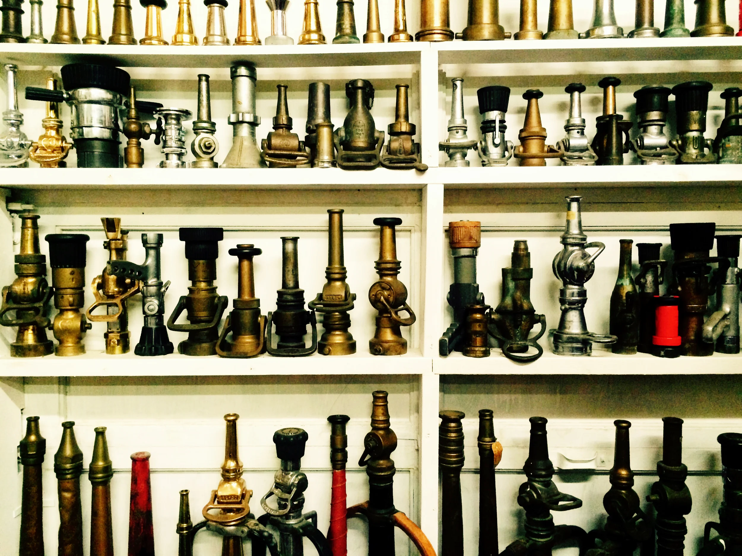
The visual example is OFD spec 2.5-inch Double Jacketed Nylon with Rubber liner. You will need a pair of internal and external calipers. (Calipers provided by late Engineer Bob Comella, OFD retired). Bob Comella has provided a wealth of knowledge to the author over the years in firematics. These tools will provide you the ability to make the necessary measurements. With these measurements one will be able to find the “true diameter” of your department’s hose. The author strongly urges you to ascertain all of these measurements, as seeing is believing. However, you only need steps 4 and 6 to attain the best results. Handling fire hose in its component parts is also an educational process in itself, providing a direct account and tactile experience as it relates to durability and construction. You will find cutting lightweight hose much easier due to the significantly less robust construction.
Step 1 (Figure A) Find the bowl diameter; it is very common for it to be 3-inches in 2.5-inch hose.
Figure A 3-inch Coupling Bowl for 2.5-inch DJ Nylon Rubber lined hose
Step 2 (Figure B) Cut hose off coupling as close as possible. Measure it. The 2.625-inch measurement is inaccurate; the material made it a difficult to measure with a ruler. Still note, it is visually larger then 2.5-inches before it is put under pressure.
Figure B - 2.5-inch hose cut off at the coupling
Step 3 (Figure C) Then reach into the coupling with a pair of internal measurement calipers and measure the diameter at the expanded expansion ring. As you can see it is 2.812 inches. This is the second visual cue that hose size creep exists, probably due to thinner jackets and liners.
Figure# C - 2.8125-inches Expansion Ring Measurement - 2.5-inch Nylon DJ Rubber Lined hose
Step 4 (Figure D) Determine the thickness of total jackets and liner material. Lightly clamped in wood, it measured 0.3125 inches.
Figure D - 0.3125-inch DJ Nylon & Rubber Liner Material Thickness in 2.5-inch Hose
Step 5 (Figure E) Use external measurement calipers to gain a diameter measurement at both operating pressure and 100psi static. No significant difference was found.
Figure E - External caliper measurement of diameter of charged 2.5inch hose
Step 6 (Figure F) Record the external diameter measurement of the hose. It was 3.062 inches. Notice it is larger then 3-inches. Some hose construction designs allow for more diameter expansion through stretching. Try to spec as close to a static/fixed external diameter hose construction under reasonable 100 to 200 psi pump discharge pressures as possible. This type of hose construction can be expected to minimize problems with liner separation, increase longevity and provide predictable friction loss characteristics.
Figure F - External caliper measurement of diameter of 2.5-inch hose
After you have attained the above information, you can gain the most accurate internal diameter measurement of the charged 2.5-inch hose. It will be provided by subtracting the Step 4 measurement of 0.3125 inches (total DJ Nylon Rubber Lined Material Thickness) from the Step 6 measurement of 3.062 inches (external diameter of the charged hose). This math yields a result of a true diameter of 2.75 inches in OFD 2.5-inch fire hose.
The author was being conservative with the caliper measurements and made sure it was snug against the hose when measuring external charged diameters. Oakland spec DJ attack hose is at least 2.75-inchs, probably a bit more if you take into account slight hose expansion when charged. Lightweight hose would cut down on jacket and liner material thickness, so the result with the standard 3-inch coupling bowl for 2.5-inch hand-line would be an even larger internal diameter. This creates a tragic “Catch-22” for lightweight hand-line hose construction. It is lighter to carry when uncharged, but heavier when charged to deploy. It is also inherently more prone to failure. Talk about a bad deal.
The internal diameter creep in modern 2.5-inch hand-line leads to a significant impact on deployment in the form of unnecessarily low friction loss for common handline flows, even off standpipes, and increased charged water weight. The weight issue is clearly denoted by Figure G. It gives internal hose diameter in 1/8ths of an inch from 2 1/2-inch to 2 7/8-inch true internal diameter hand-line. Note the roughly 70 pound weight difference between the smaller and larger of the listed line sizes. Chiefs, spec your hose wisely for your rank and file!
Figure G - Water weight difference in 2.5-inch fire hose with different internal diameters
What size diameter “true hose” line do we need?
The Nozzle Dreams article reached this point and developed a two choice nozzle system that is based on simplicity, physics, and community fire loading. As of now, 1¾-inch and 2½-inch (roughly 1.85 and 2.75 inches respectively) are the two most commonly used attack hose-line sizes in the United States. There are strong arguments for a minimum flow difference of 100gpm between a fire department’s handline attack packages.
Table#5 represents the three key factors whose interrelation dictates the degree of effectiveness of attack hand-line fire streams. These factors are flow rate or gallonage, nozzle reaction force (RF), and horizontal reach. The color scheme in Table#5 dictates that red highlighting represents negative consequences. The green highlights represent positive consequences. The yellow highlighting represents the limits of flow and nozzle reaction for hand-line operations. The table is broken down into two nozzle systems. Each system is based on a given department’s choice of complimentary sizes of the smooth bore tips for its small and large attack hand-lines (or fixed 50psi Fog Nozzles). One system is based on the choice of 7/8-inch and 11/8-inch tips. The other is based on the selection of 15/16-inch and 13/16-inch tips. This shall be referred to as the rule of eighths and sixteenths.
Table #5 - The rule of 1/8ths and 1/16ths is a simple two nozzle system for fire service hand-lines
A key component of a hand-line attack package is that it must be deployable as a true interior attack hand-line. Charged hose-line weight is a large factor in deployability, note in table 5 the far left side is hose size. True internal diameter, 1.75, 2, or 2.5-inch, DJ hand-line probably does not currently exist. Remember, when examining Table 6 below, it has been well established that 69 pounds is the largest acceptable reaction force for small attack-line operations. This allows for a deployable fire stream of 185gpm at 50psi nozzle pressure. Also, 111 pounds is the upper limit of reaction force for a large hand-line with a flow of 295gpm at 50psi. Please take note that hand-line operating pressure should ideally not exceed 200psi and more normally operate in the 100 to 150psi range. The author also acknowledges that many factors on the fire ground can realistically lead to a range of nozzle pressures. Hence, the 40 to 60psi nozzle pressure spread provided in Table#5. We must not get bogged down in a system that requires perfect execution, this will lead to failure on the battle ground. Where pump operators, officers, and hose-line members are operating in a task saturated and time compressed environment, efficient simplicity is the key to effective attack package deployment. As much as possible should be addressed before contact with the enemy.
Notice that the 1-inch tip flowing 210gpm generates a reaction force that is high for a small hand-line but low for a large handline. Essentially, it leaves flow under-developed in a properly staffed large hand-line, but it has a reaction force too great for a lightly staffed hand-line of 2 firefighters. The 1-inch tip flow of 210gpm has largely been abandoned by the fire service. It has had a recent resurgence, but it is probably an off-course idea. The color scheme in Table# 6 dictates that red highlighting represents negative consequences. The green highlights represent positive consequences. The yellow highlighting represents less than acceptable flow (below 250gpm is used for commercial fires and standpipe operations) and heavy charged hose-line weight for a lightly staffed line. Note in table 6, a perfectly good 240gpm stream can be produced with the same reaction force of 79 pounds using a 1 1/8-inch tip. The 1 1/8-inch tip used in this manner, under pressurized at 40psi, leaves a significant reserve capability of developing a true large flow fire stream of 250gpm or greater. This is what the author recommended to the FDNY for their “actual 2.2-inch” 50 foot standpipe pack hose. It is the authors understanding that this hose is now used as the lead length for tenement standpipe operations utilizing a 1-inch tip. Advice was also given to take a closer look at the diameter of their 2.5-inch hose spec, which is likely where answers to the deployability issues truly lie and greater department-wide benefits could have been realized, by operating with a “true 2.5-inch diameter handline.”
This would have also aided departments nationally. For often, as the FDNY goes, so go many of the nation’s urban fire departments and equipment manufacturers. There are many issues revolving around this move in the FDNY and as an outsider one can not know all of the facts even when invited to comment and given some background. Some department members have made it clear that, in their opinion, in the past tenement fires were dealt with using an attack package consisting of a lead length of FDNY 1.75-inch hose (1.88inch) with a 15/16th tip (185gpm) filled out with 2.5-inch hose. Many considered this flow more than adequate for fire control and extinguishment at certain tenement standpipe fires. Those outside of the FDNY must take into consideration that there are no pressure regulating valves (PRV) on standpipe systems in New York City. As per city code, there are only pressure reducing devices (PRD). SOPs dictate that Members remove PRDs for standpipe operations. This means that achieving higher standpipe outlet pressure is only limited by the test pressure of the system. Contributing factors of flow path control and line management issues where brought up extensively when talking about failure and success in tight stair and hallway configurations found in tenement type buildings in the City of New York. It is very commendable that the FDNY is attempting to address these issues; their efforts in these matters are probably not yet exhausted.
Table#6 -“True Diameter Hose” Handline Selection Tab
RF = 1.57 x (D)sq x NP GPM = 29.7 (D)sq √NP (Fornell)
What has eluded Miami-Dade and FDNY, and so many others, is that they are fielding 2.5-inch hose that is probably at least 2.75-inches. This adds 70 more pounds of water weight per 100 feet than necessary. Additionally, much of the rest of the fire service deploying 2.5-inch “mystery hose” is using traditional hydraulic formulas or pump charts and over pressurizing nozzles. This leads to excessively high flows and nozzle reaction forces. Many who flow test 2.5-inch “mystery hose”, discover a low friction loss per 100 feet, which leads to low pump discharge pressures at 265gpm flows. This leads to low residual pressure in 2.5-inch “mystery hose”, which increases kinking and line management issues.
You may note a 1 1/8-inch tip with a 265GPM flow at 50psi NP generating a substantial friction loss of 45 psi per 100feet hose, deployed on 2-inch true handline hose in Table #6. Fire departments that routinely operate from standpipes or deploy lengthy stretches of large flow handlines would be better serviced by a return to a true diameter 2.5-inch hand line hose. The recent focus on having hose manufacturers create a “2-inch mystery hose” actual 2.25-inch diameter hose, may be a misguided attempt to overcome the problems created by“hose diameter creep” in current 2.5-inch DJ handline fire hose, which is 2.75-inches in actual diameter and larger. Efforts should be made nationally to address this problem first, before the need for 2.25-inch hose is evaluated.
The ideal attack hand-line hose diameters for a fire department will depend on their selection within the range of small hand-line flows (160-185gpm) and within the range of large hand-line flows (250-295gpm). It is critical to keep one size of hose for large attack hand-line flows. The hose must be of a size that is practical to deploy from a large static bed to facilitate multiple lengthy stretches without having to deal with a different size lead length of hose. This is the ideal! The hose must be of a size that will work well for standpipe operations and deliver an adequate flow when deployed from a standpipe outlet with a PRV set to 65psi. That hose does not need an internal diameter of 2.75-inches or the new 2.25-inch lightweight hose diameter. Physics dictate the answer again. The hose-line needs to be 2.5-inchs in diameter. No more, no less. This is based on the commercial hand-line fire stream goal of 250-300gpm. It is with good reason that it was that size to begin with.
To add clarity to the line selection process, this article adds two items under “L” in the A.D.U.L.T.S. list of conditions necessitating the use of 2.5-inch hose.
A — Advanced Fire Upon Arrival
D — Defensive Operating Mode (Defensive Operations)
U— Unable to Determine the Extent (Size) or Location of the Fire
L — Large, Uncompartmented Areas, Lengthy Stretch, Low Pressure Possibility
T— Tons of Water(One ton of water per minute with a 1-1/8” tip)
S — Standpipe Operations
An A.D.U.L.T.S diameter hand-line hose must be capable of a large flow that will work on standpipes and for very lengthy stretches while maintaining deployability. This should be a call to return to the “true 2.5-inch hose”. All other special situations can easily be addressed by filling out true 2.5-inch DJ hose with 1.75-inch or 2-inch DJ fire hose. Remember to keep it simple. Members pump these handlines under less than ideal conditions. In the OFD, a pump operator needs only to remember four numbers 50, 30, 10, 5. All nozzle pressures are 50 psi. 30psi per 100 feet is the friction loss in 1.75-inch hand-line hose (160gpm). 10psi is the friction loss in 2.5-inch hand-line hose (265gpm) per hundred feet. Lastly, 5psi is the friction loss in 2.5-inch hose per 100 feet when used to fill out 1.75-inch hose line.
Table 7 is the first three lines of the OFD pump chart with a picture of the rear static bed. It is color coded to reflect the proper hose line. We must set our people up for success. Unnecessary complication on the battle ground of a structure fire, may rapidly lead to a series of cascading failures ultimately leading to inability to extinguish the fire at the seat in a rapid fashion. Line selection for the officer between small, 160gpm, and large, 265gpm, flow should be clear. Lengthy stretches should be easily attainable in both small and large flow hand-lines allowing the crew to focus on getting the nozzle to the seat of the fire. No hose-packs or wyes should be necessary to deploy hose from the pumper. Ideally there should only be two shut offs in a deployed line, one at the pump panel and other the other at nozzle.
Table# 7 - Partial OFD Pump Chart and Picture of Rear static loads
The fire service members are the end users of the product. One is hard pressed to think of any other industry that allows this degree of manipulation in an engineered product. Water main systems we rely on are all mathematically developed based on known internal pipe diameters and friction loss coefficients. Can you imagine ordering a 30 foot ladder and being delivered a 33 foot ladder? People would immediately complain. Many respected instructors in this field, including Curt Isakson, Ray McCormack, John Ceriello, Jay Comella, Daryl Liggins, Jerry Herbst, Jason Blake, Jeff Shupe, Jerry Knapp, David McGrail, Dave Fornell, myself and others teach that you must flow test your hose to determine friction loss. This wrongly suggests that hose is magical and somehow deviates from known hydraulic formulas. It’s the hose, not the formula that is lying. “Mystery Hose” has been created by many influences. The path to this dysfunction was paved with bricks of good intention. Only the truth and transparency will put us once again on the right path! We must demand it! Only a change to the NFPA 1961: Standard on Fire Hose, where language such as “hand-line fire hose (2.5-inch and smaller) will be within a 1/16th of an inch of what is printed on the jacket at 150psi operating pressure and never exceed a 1/16th of an inch of what is printed on the jacket below 300psi”, will solve this problem.
Which Chief or Department will stand up and be the first to return out of spec hose? Which manufacturer will end this shell game and ensure honesty with a “true hose jacket diameter marking”? There has been a real cost to this “hose diameter creep”. Operating with a hand-line larger than needed for the developed flow creates or exacerbates many line management issues including increased kinking, additional water weight in the line, increased nozzle reaction force, and greater difficulty in flowing water whilst advancing the line. “Hose diameter creep” has national impact, as countless slowed fire attacks lead to increased property damage and endangered lives.
The fire service would be well served by three true hose diameters of 1.75, 2 and 2.5-inch. The vast majority of the fire service need only to field true hose diameters of 1.75-inch and 2.5-inch. This hand-line fire hose should be of traditional construction with a double-jacket of nylon or polyester and a rubber liner. Hose of this construction should carry a minimum 10-year warranty. This provides the lightest possible charged hose weight, while ensuring the robustness, durability, and reliability inherent in traditional hose construction. Maneuverability is well served and quick attack bread and butter residential fires can be combated with appropriate flows of 160 to 185gpm through true diameter 1.75-inch hose. A true diameter 2.5-inch hose has the versatility to function at all A.D.U.L.T.S fires, and reclaims the mobility it has lost over the years due to “internal diameter hose creep” having burdened members with up to 70 pounds of unnecessary water weight per 100 feet of hose.
It is the author’s intent to fix this problem on a national scale. The coefficient of friction loss for smooth PVC plastic pipe was used in the above examples and an online Hazens-Williams hydraulic formula calculator. PVC plastic pipe coefficient was intentionally selected in order to give fire hose manufactures the best possible scenario. The results clearly show that hand-line fire hose is commonly cheated up in size above the marked jacket diameter. This is one of the largest problems facing the fire service. As we increase our fire flow to deal with higher heat release rate in modern fire loading, most of us have addressed reaction force by lowering nozzle pressure. The fire service must strive to reduce hardships members collectively suffer while advancing hose-line on the fire ground. In the end, members deploying large flow handlines are reaction force limited to roughly 110 pounds produced by 295gpm at 50psi. Physics dictates that the fire service should not be fielding a hand-line with a diameter larger then 2.5-inchs.
In solidarity,
Dennis LeGear
Works Cited
Bill, Nemick“A 2 ½-Inch Alternative?”. New Jersey: Fire Engineering 1 October 2013
Corbett, Glenn. Editor Fire Engineering’s Handbook For Firefighting I and II. Oklahoma: PennWellCorporation. 2009
Fornell, David P. Fire Stream Management Handbook. New Jersey: Fire Engineering. 1991
Gustin, Bill“High Rise Buidlings”. New Jersey: Fire Engineering 1 April 2013
“Know Your Flows”. Key Hose. Website. http://www.keyfire.com/pdf/knowyourfows.pdf
Online Hazens-Williams Calculator. Engineering Tool Box Website. http://www.engineeringtoolbox.com/hazen-williams-water-d_797.html
Noted Contributors
Jay Comella (Capt. Oakland Fire, ret.) -for editing, adjustment to prose, conceptual consultation.
Curt Isakson (BC Escambia Fire) -for motivation and consultation.
Veronica Wunderlich (ES, Dept. Water Res., CA) -for grammatical editing.
Other Instructors Mentioned in Article -for advancing and pushing my curiosity